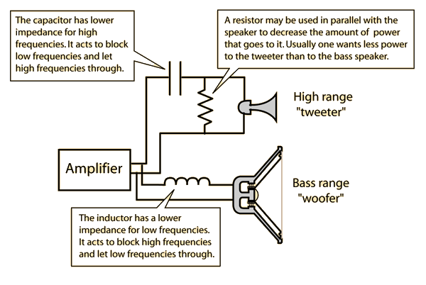
Crossover help?


Hi to all I'm hoping someone might be able to help.

I've tried to upgrade components within my crossover and now have no HF signal.

The tweeter checks out.

I've searched for bad joints , shorts etc but can find nothing obvious.

Today I've pulled the upgraded components from the Hf circuit but still have nothing.

Using a continuity test its all good up to the main cap and after back to the terminal.

I do get a bleep from both terminals so assume thats the parallel resistor.

I'm at a loss as to why its gone completely dead.

Anyone got ideas how to check the network front to back with only a basic multimeter?


Thanks in advance if someone has some ideas

Regards Ian


notdeadyet

I'm assuming you're talking about a passive crossover within your speakers, correct? Could you post some photos? Or a schematic of the original crossover? We can figure this out with just a multimeter.

I do get a bleep from both terminals so assume thats the parallel resistor.

I think you wired the high pass crossover wrong. If there’s a parallel resistor, it should be after the capacitor and connect across the tweeter +/- terminal.

If the parallel resistor wired in front of the capacitor across the input side +/- terminal you will get a bleep on continuity test. If that’s the case, the resistor "shorted" the high pass crossover input hence no HF signal reach the tweeter.

Are the parts point to point wired or circuit board? If board, you may have a lifted solder pad, possible short to ground plane etc… please let us know. Pics would help greatly. .

How do you attach images? 

It links to a url rather than to a location on the PC.


by the way, the capacitor will never test positive on a "continuity tester" because it's not really an absolute connection.  You can try testing for capacitance if you are an LCR multimeter.