Wiring 2 outlets to 2 dedicated 20 amp circuits with a single 10/3 electrical wire.


Here's an idea (and it is code compliant), using one 10/3 romex electrical wire (three insulated conductors, and a bare ground wire - 10 gauge), you can wire two outlets to a double pole breaker (and yes the legs would not be the same, which on a quiet electrical system is not a big deal).
 

In this situation, 2 hot wires from the outlets would be wired directly to each of the circuit breakers, the neutral would be bridged between the two outlets and then connected to the appropriate spot on the panel, and the grounds for each outlet would be attached to the single ground wire that goes back to the panel.  This would all appear within a quad outlet wall panel (ie. Two 20 amp outlets side-by-side)

For a long 70 foot run this seems prudent thing to do, less costly and kosher.

emergingsoul

@emergingsoul ,

Look at the first schematic diagram below.

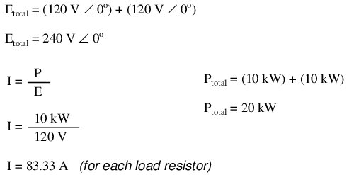
Note: Load 1 and load 2 are identical. The loads are Balanced.

Note: The shared "neutral". 0 A (The shared neutral is not involved).

Load 1 and load 2 are in series with one another and are fed by 240V


Addition of neutral conductor allows loads to be individually driven.


Instead of a single 240 volt power supply, we use two 120 volt supplies (in phase with each other!) in series to produce 240 volts, then run a third wire to the connection point between the loads to handle the eventuality of one load opening. This is called a split-phase power system. Three smaller wires are still cheaper than the two wires needed with the simple parallel design, so we’re still ahead on efficiency. The astute observer will note that the neutral wire only has to carry the difference of current between the two loads back to the source. In the above case, with perfectly “balanced” loads consuming equal amounts of power, the neutral wire carries zero current.

Notice how the neutral wire is connected to earth ground at the power supply end. This is a common feature in power systems containing “neutral” wires, since grounding the neutral wire ensures the least possible voltage at any given time between any “hot” wire and earth ground.

An essential component to a split-phase power system is the dual AC voltage source. Fortunately, designing and building one is not difficult. Since most AC systems receive their power from a step-down transformer anyway (stepping voltage down from high distribution levels to a user-level voltage like 120 or 240), that transformer can be built with a center-tapped secondary winding: (Figure below)


American 120/240 Vac power is derived from a center tapped utility transformer.

https://www.ibiblio.org/kuphaldt/electricCircuits/AC/AC_10.html

/ / /

Note: See the two 120V rectangles?

Connect a 2A digital load across one and a 2A analog load across the other. 0 amps will return on the shared neutral. the two loads are in series and are fed by 240V


Jea48

Why are you talking about a step down transformer? this is a multi branch circuit involving 2 outlets, and a double pole breaker.

Appreciate all the commentary but my God, wtf?


@jea48 was referring to the transformer that steps your neighborhood’s distribution lines (which are at multi kV voltage, probably at least 3 kV and more likely 6.6 kV or more) down to 120/240VAC.

@emergingsoul

I’m beginning to think you are just pulling my chain here...🤔

Where does the power that feeds your house come from?

A Utility Power Company?... Somewhere outside your House there is a step down power transformer that feeds power to the electrical service of your house...

Without a Single Phase 120/240V SPLIT PHASE power system there would be no 3 wire single phase multiwire branch circuit... Can’t have a 3 wire multiwire branch circuit without a split phase power system. The Utility Power Company’s step down power transformer’s center tapped 240V secondary winding is what creates the 120/240 split phase power system.


/ / / /


You asked Why?

Not sure why this would be happening.


jea48,

You say that, Zero amps will return on the shared neutral conductor to the source).

Not sure why this would be happening. And then from this point on in your response above I sort of lose an understanding of what you’re saying.

But I’m really trying to follow. And I think for many it would be nice to know the rationale here as well, as this is a very profound issue.


Remember This Post:

Jea48 said:   (12-21-2022 at 08:46am)

A multiwire branch circuit is basically an extension of the split phase winding of the utility power transformer.


.

Post removed