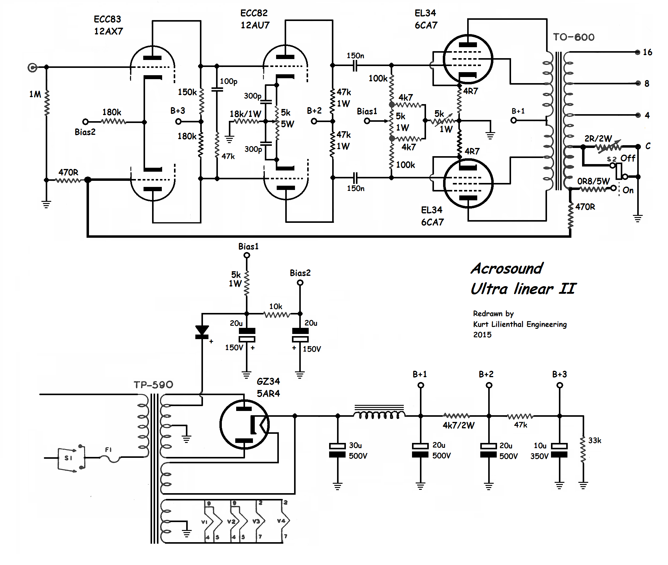
Acrosound UL-II schematic. Note the input 12AX7 is direct-coupled to the 12AU7 driver stage, so DC drift from internal 12AX7 mismatch could be a problem.
Technical analysis: The input signal goes to the top half of the 12AX7. The bottom half is connected to the feedback signal, which comes from a dedicated winding on the output transformer. The feedback summation occurs across the paired cathodes of the 12AX7. The plates of the 12AX7 are direct-connected to the grids of the 12AU7 driver.
There is a HF phase-adjust circuit from the 100 pF cap in series with the 47K resistor. This improves the stability of the feedback system. The 12AU7 driver has a 5K 5W current-balancing pot in the cathode circuit, most likely to correct for any DC imbalance of the 12AX7. I suspect the 300p marking of the bypass caps on the 12AU7 is in error. This should be 2 to 10uF, whichever gives the best square-wave response.
Similarly, there is a DC balance pot in the Bias 1 grid circuit of the EL34 output tubes. The 4.7 ohm series resistor in the cathode of each EL34 is there to meter current, which is adjusted by the 5K pot. Although not drawn, there would be test points for each cathode to ensure the correct bias point.
Although not marked as such, this is a fixed-bias output section set up for Class AB (high power) operation. Correct bias setting for each EL34 is essential for long tube life.