@holmz
While I'm not certain, I think @dover may be referring to the reaction of the square wave to various loading, resistance, and capacitance properties, when dealing with SUT, which is found on that same Rothwell Audio Products site:
"
 |
| |
| |
figure 1a
|
|
|
|
|
|
 |
 |
| |
Transformer ringing
All transformers have limitations due to the inevitable capacitance between windings, leakage inductance etc. and these determine the transformer’s bandwidth and can produce “ringing”. Ringing can be seen as overshoot at the corners of a squarewave, as illustrated in the figures above. A lower load impedance on the transformer's secondary winding has two effects: reduced output and damped ringing. This perhaps explains why people attempting to tune their system by ear have reported that loading resistors (intended to load the cartridge correctly) have a beneficial effect. However, in reality the improvement in sound quality isn't due to the cartridge being loaded correctly, it's due to the phonostage being overdriven less, and due to transformer ringing being damped.
A much better approach to optimising sound quality would be to separate the two issues and deal with them individually. Overloading the phonostage would be addressed by using a transformer with a lower turns ratio, and that alone would have the added benefit of better performance. Ringing can be dealt with by employing a suitably chosen resistor-capacitor network without the penalty of excessive signal loss. In the case of the Ortofon Vivo Red in the example above, a reduction in output voltage is a benefit, but more often than not it isn't a benefit. With cartridge's such as the Denon DL-304 with its feeble 0.18mV output, any loss of signal voltage caused by attempting to damp ringing with a resistor is unwelcome. Achieving the correct signal level is one issue and damping transformer ringing is another. Trying to treat both issues with one cure isn’t advised. Fortunately, ringing can be damped by a suitably chosen resistor-capacitor network without the penalty of a reduction in output.
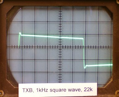
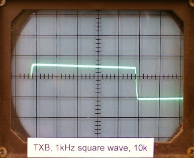
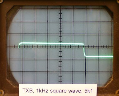
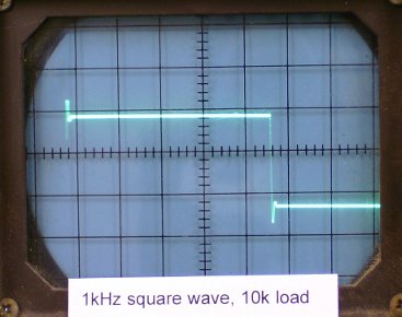
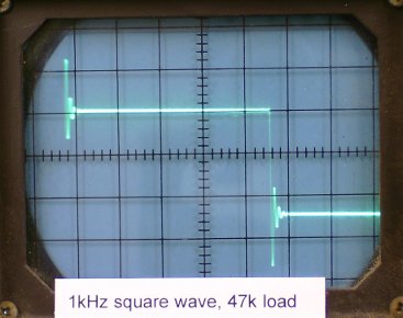
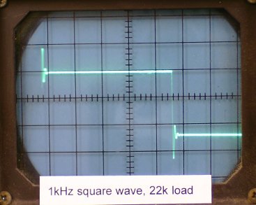
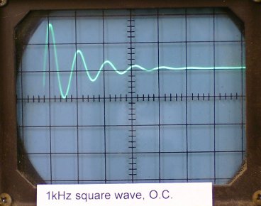
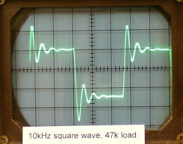
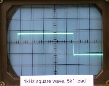
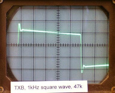
The oscilloscope screen shots in figure 1 above illustrate ringing and the effects of different loads on the transformer's secondary winding.
Figure 1a shows the output with a 47k ohm load on the secondary of a fairly modest transformer. The slope on the top and bottom of the waveform is caused by the low frequency limit of the transformer due to inadequate primary inductance. The peaks at the corners of the waveform are due to transformer ringing, also known as overshoot. Figures 1b, 1c and 1d show what happens to the waveform when the secondary load is reduced to 22k, 10k and 5k1 respectively. The slope of the waveform straightens out as the impedance is reduced and the corners lose the unwanted peaks, but the overall signal level also drops significantly. The level with the 5k1 load is about 10dB less than the level with the 47k load. This shows that although the performance of the transformer can be improved by reducing the load impedance, the benefit comes at the expense of a serious loss of signal level. Since the point of using a step-up transformer with a moving coil cartridge is to gain an extra 20dB or so of signal level, any loss due to incorrectly loading the transformer is unacceptable.
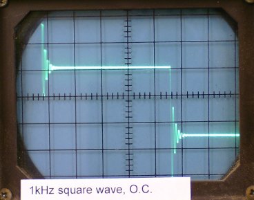
The transformer ringing which can be seen as peaks at the corners of the waveform in figure 1 is a common problem and arises from inductive and capacitive elements (leakage inductance and inter-winding capacitance) combining to produce resonance. The capacitance of the cable connecting an mc step-up transformer to the following phonostage also plays a part, which is why the interconnecting cable should be a low capacitance design and kept as short as is practical. Ringing can be found in many commercial moving coil step-up transformers, regardless of price. Sometimes the ringing occurs at very high frequencies and is reasonably well damped and therefore quite benign, but often it occurs at a much lower frequency or rings for such a long period that it can cause quite audible effects. Even expensive transformers from well-known audiophile brands often exhibit poor performance as regards ringing.
Figure 2 below shows oscilloscope screen shots of a step-up transformer from a manufacturer of expensive valve amplifiers. The input signal is again a 1kHz square wave from a 10 ohm source. Figure 2a shows the transformer's output when there is no load and the overshoot is quite clear to see. Figures 2b to 2e show the 1kHz waveform with different loads on the transformer's secondary. A 47k load has barely any effect on ringing, but as the load is reduced through 22k, 10k and 5k1, the ringing is progressively damped. At 5k1, the ringing is gone but the signal level is reduced. With this particular transformer, the signal loss with the 5k1 load is not as bad as the signal loss suffered by the first transformer, but any loss of signal should be avoided. Note however that the top and bottom of the waveform are very flat, indicating that this transformer has very good low frequency performance. Figure 3 is a closer look at the corner of the waveform and shows clear ringing which lasts for several cycles before subsiding. The frequency of the ringing is about 100kHz - well above audibility - so there's no chance of actually hearing a ringing sound, but it is clear that the signal produced by the signal generator is being severely deformed. Figure 4 shows the output from a 10kHz square wave input. The waveform is hardly recognisable as a square wave at all and it is not difficult to imagine what effect such deformation could have on a music signal. The leading edges of crash cymbals, ride cymbals and snare drums or the attack of plucked strings could easily lose integrity and become a confused jumble of sound. When several percussive instruments are playing together, as is very common, separation between the instruments will not be helped by the severe ringing shown in figure 4.
|
|
|
|
|
 |
 |
| |
figure 4
|
|
|
|
 |
 |
| |
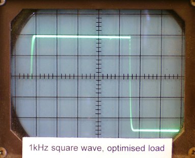
Fortunately, ringing can be totally eliminated without sacrificing signal level by loading the secondary winding correctly with a resistor-capacitor network, not a simple resistor (though far too many commercial step-up transformers totally neglect this). Although lower values of resistive load on the secondary do tend to reduce ringing, as illustrated above, loading with a correctly optimised resistor/capacitor network will produce far superior results. Since different transformers are constructed with different core materials, wire thickness, number of turns and winding techniques, the optimum load network will be different for each, and the only way to determine the correct network is through measurement.
Figure 5 below shows the transformer of figures 2 and 3 after an optimised load network has been applied, again with a 1kHz square wave input. The ringing has been eliminated and the signal level available into a 47k load has been maintained.
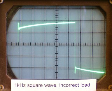
Figure 6 shows the effect of applying a non-optimum loading network. In this case the incorrect component values (out by only a few nanofarads and a few kilohms) have resulted in quite a peculiar deformation of the waveform. This illustrates the need to get the loading network right rather than copying a network which is optimised for a different transformer.
As an aside, the use of silver wire for the windings might appear impressive but does little or nothing for performance due to the fact that silver has only marginally less resistance than copper and the limiting factors in transformer performance are due to the finite size and permeability of the core, leakage inductance and inter-winding capacitance, none of which are improved by the use of silver wire. However, it does have a significant impact on cost. It should go without saying that elaborate cases with 3D milled aluminum front panels or gold plated turrets, while very nice to look at, also have no benefit for audio performance but, again, do have an impact on cost.
|
"
|
Dear @phoenixengr : " My point about the specified impedance along with the output voltage was to make the necessary gain calculations easier. "
I was very clear and stated that my phonolinepreamp is an active high gain design and I can tell very good design or at least competitive today.
Why should I care about gain when here I explained and told you that " other that SPL changes " whic other advantages? and I posted that we had not changes in FR.
I'm not talking of phono stage + SUT.
R.
|
|
I am trying to figure out:
- whether they generated a square wave with the same output impedance as the cart and fed the SUT with that.
- Or if they had a test LP with a square wave
- and then if it is a test LP is that square wave a triangular shape on the track to make an electrical square wave.
?
|
@holmz
this one -
- whether they generated a square wave with the same output impedance as the cart and fed the SUT with that
|


