Tube PHONO preamp interference - RFI, EMI, bad grounding?


Hello!

My tube phono is picking up interference most probably from the air. It's EAR yoshino 834p, using three 12AX7 tubes. It's sounds pretty amazing and I willing to try everything to keep it. 

Here is a sample of the sound - 


The rest of the setup is ARC LS16 mk1, Classe CA200, Chord Qutest, Technics SL1200 with Nagaoka MP200, Tannoys D700

I have tried many things already -

- grounding the phono to the preamp, grounding the phono to a socket, covering the phono with a pot, saucepan - no change

-plugging the phono preamp alone into an integrated (Bryston B60) and removing other stuff.

- the important part is I have taken the phono to two other places and it worked perfectly fine, even with the cheapes cables.

- I haven't had any problems with previous phono preamps which were all solid state. 

- if I unplug the turntable the signal fades to about 50%

- if I try different RCA cables, there's not much of a change even they are shielded (audioquest mackenzie, supra etc.)

- the signal also fades when I grab the cables. Also works if I grab or squeeze the output cables. 

- I have tried to wrap the cables into aluminum foil, I have noticed a difference but it's still unlistenable.

- I have tried pluging in a 5 meters long RCA output cable and walked with the phono preamp around the room. It's simply like carrying an antenna. Placing the phono on the floor helps but again, the interference is still present. 


Do you have any suggestions what else to try? Is there some kind of grounding that would prevent the phono preamp acting like an antenna? 

I haven't tried a new set of tubes yet. 

I think the 12AX7 are simply too sensitive to all the mess in the air. The ARC LS16 preamp was catching the same signal very quietly when I took it's cover of. 

Thanks!

Filip
128x128filipm

@dover It’s the other way around on the EAR I guess.

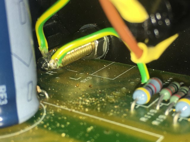
Here is a picture of the ground binding post. The wire on the right is connected to the circuit board. The one on the left leads to the IEC through the 33 ohm resistor.

That means the chassis relies on the grounding pin and not so much on the ground to the IEC, correct? Nevertheless, I have tried grounding the chassis using this pin and separate wire leading to the socket ground pin, a heater, chassis of the ARC preamp.. none of these made a difference. Maybe I was just using a poor wire (the was almost no resistance on that wire).

I guess things could change if this 33 ohm resistor was moved to the wire on the right - between the grounding pin of the chassis and the circuit board ground. Then the ground of the RCA connectors would be closer to the ground of the inlet and not the circuit board.

@filipm 

Yeah so I can see that both the ground post and circuit board are all earthed through the 33ohm resistor. If the chassis and earth post measures 0 ohms then the chassis is lifted above ground ( not what you want ).

The chassis could be connected to the circuit board ground anywhere - it could be the binding post;  ?you would need to look around - are there any wires to the chassis ? It could be through circuit board legs ?

I would do the following test -

If you desolder the 2 green and yellow wires from the grounding post but leave them soldered together - then the circuit board would is still grounded through the 33 ohm resistor ( assuming you have reattached it ).

Now measure from the green wires to the chassis. If that measures open circuit then you would know that the chassis is earthed through the ground post mount.

Double check by measuring the chassis to mains earth tag - should be either 33ohms or open circuit. If it is 33 ohms the chassis must be earthed via the board somewhere else. If it is open circuit then we now know the chassis is earthed through the ground post mount only.

Depending on your test results I could suggest a very easy fix for you to the earthing issue. This may or may not fix your noise issue though, but in my view would be worth trying.

@dover the chassis and the board are connected by those green wires. 

board > right green wire > binding post < left green wire - 33ohm resistor - ground pin of the IEC. (which means the left and right wire are meeting in the binding post)

also, there are screws holding the board but they are not touching the circuit of course. 

There is a possibility that the joint of the board ground (where the circuit board and the grounding wire meet) needs to be resoldered. 

If I desolder the 2 wires it only means the chassis would be completely lifted from the ground. The chassis and these wires wouldn't be even electrically connected. 

What's your suggestion?

Let's not forget the error may not be in the preamp. It's working fine anywhere else but my place. Maybe it just needs better grounding from the binding post. But where to attach it if not the socket ground pin? I have no idea. 

(It's possible the grounding problem leads further - maybe the sockets are poorly grounded. Maybe there's a problem in the main switch. We still haven't measured that, if it's even possible. I'm waiting for the electrician to show up.)

@filipm 

If I desolder the 2 wires it only means the chassis would be completely lifted

Thats likely correct - but it would be prudent to verify that. I say  this because most of the time ground posts are insulated from the chassis, and there may be a different path we cant see.

If proven to be correct, and the chassis is now floating, then you would be able to earth the chassis to the incoming mains earth pin before the 33ohm resistor and achieve much better shielding - as per @atmasphere suggestion in his earlier post.


@dover I think If I wanted achieve the best shielding possible I'd have to leave the two green wires as they are but to cut out the 33ohm resistor. Then everything (the board, the chassis) would be grounded through the IEC with no resistance. I may be wrong, please take in account I'm a noob at this and I'm often missing what for others is common knowledge. So maybe if I cut out the resistor, it will lead to a ground loop.
I think if I unsoldered the green wires from the pin and soldered them together, I'd just ground the board while the cage would be left absolutely unshielded.